The industrial control system (ICS) used in this scenario simulates an environment that might be used to cool industrial equipment. The ICS is made up of five systems. The first system contains a tank, tank level sensor and a water pump. The second system is a programmable logic controller (PLC) which controls the water pump based on the level of water found in the attached tank. The third system is an Open Platform Communications (OPC) server which accesses and modifies data found on the PLC. The fourth system is running Human Machine Interface (HMI) software which communicates with the OPC server to provide a human system operator with system statistics and control. The final system in the ICS is a security appliance that provides routing and firewall services for all systems.
This scenario also make use of a system running Kali Linux. In this lab the virtual network switch is configured so that the Kail system receives all data transmitted. (Network diagram)
In this lab you are going to observe that when a hacker is connected to the same network segment as the ICS systems, they are easily able to view data being shared between all devices. After verifying this you will move the hacker system to its own network and again attempt to view data being transferred. You will discover that when a hacker is connected to a different segment then the ICS systems they are no longer able to view data transfers.
Part 1
Install Systems
In this part of the lab you are going to install and configure the systems needed to complete the lab.
Login a second time to the nlstu-s1.nl.northweststate.edu remote server using your assigned username and password.
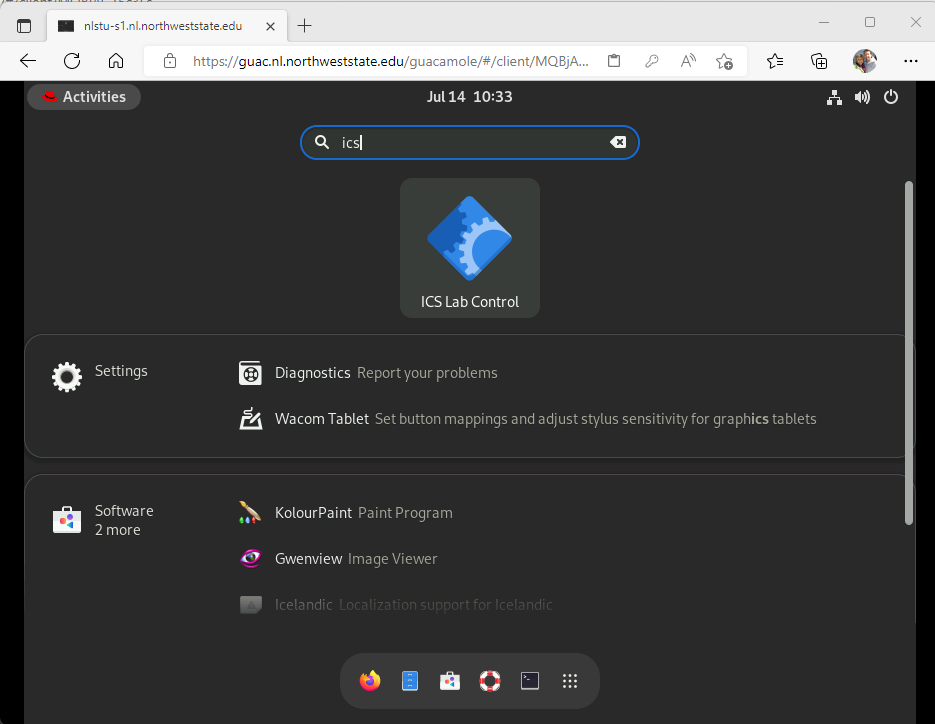
When the Linux desktop appears, click the Activities menu located in the top left hand corner of the screen.
Type ics into the Type to search field that appears in the top center of the screen (Example).
Click the ICS Lab Control icon.
Select the New Lab option, click the OK button then wait for the systems to start.
Part 2
Login and verify connectivity
In this part of the lab you are going to login to the hacker system, view the system's IP address and verify that it can connect to the PLC.
Access the Kali system.
At the login screen enter student into the Enter your username field and Password01 into the Enter your password field.
Click the Log In button.
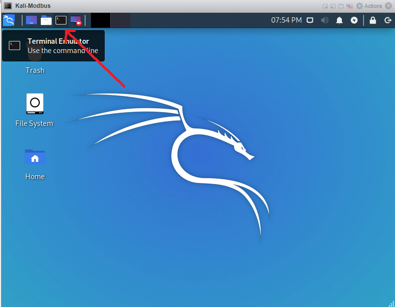
Open a terminal (command prompt) window by clicking the Terminal Emulator button found at the upper left hand corner of the window (Example).
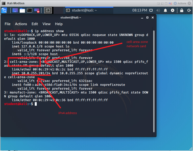
View the network address of the system by typing the command ip address show (NOTE: You must press the <ENTER> key after typing a command).
Examine the output of the command and find the IPv4 address associated with the active network card viewing the inet value associated with the network card labeled cell-area-zone (Example).
Notice that the system contains multiple network cards. Network card 1: labeled lo: is the loopback card which is used for internal communications and testing, network card 2: labeled cell-area-zone: is the card connected to the Cell/Area zone along with the ICS systems, network card 3: labeled manufact-zone is currently disabled (DOWN) and is connected to the Manufacturing zone network segment which is separated from the ICS systems by a router/firewall.
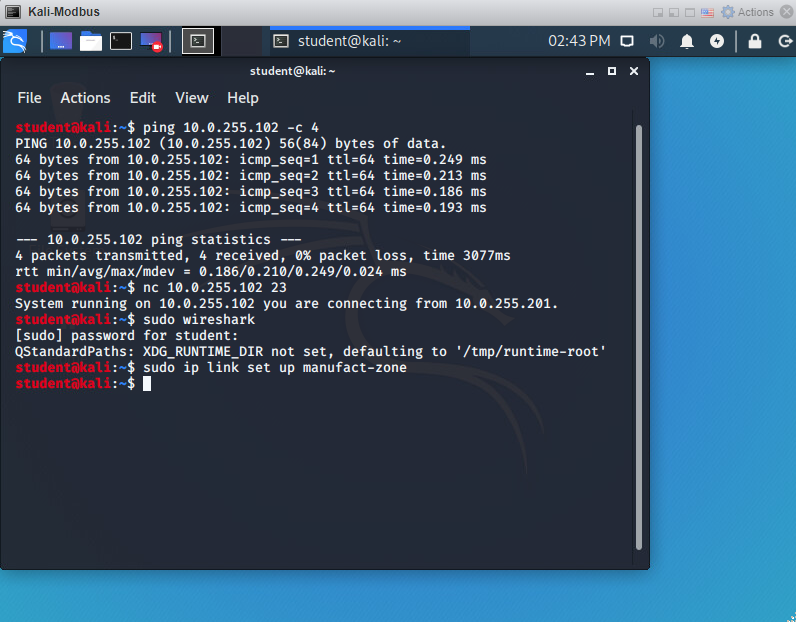
Verify that the hacker can communicate with the PLC by typing the command ping 10.0.255.102 -c 4 and observing that 4 packets are transmitted and 4 packets are received.
Verify that the PLC is running by typing the command nc 10.0.255.102 23 and observing that the PLC is running, and that the IP address of the PLC and the address of the connecting system is shown.
The nc command starts the netcat program which is a useful network utility that allows a quick connection to network services. In this case netcat is connecting to the telnet service running on the PLC.
Note that the Kali system is on the same IP network (10.0.255.0/24) as the ICS systems (10.0.255.0/24).
Part 3
Capture and view data transmitted in the Cell-Area zone
In this part of the lab you are going to use the Wireshark network monitoring software to capture and view data being transmitted on the Cell-Area zone.
Start the Wireshark program by typing the command sudo wireshark.
The Wireshark program requires administrative privileges to the system, since you are currently logged in as the student user you must indicate that you wish to use administrative privileges prefixing the command to be executed with sudo.
Authenticate to the system by typing in the password Password01 followed by the <ENTER> key.
To prevent people from looking over your shoulder and writing down the password it will not be displayed as you are typing.
After the Wireshark program starts select the cell-area-zone network device to indicate that you wish to capture data on that device.
Click the Capture menu then select the Start option.
The data you need to view will be captured very quickly so immediately return to the Capture menu and select the Stop option.
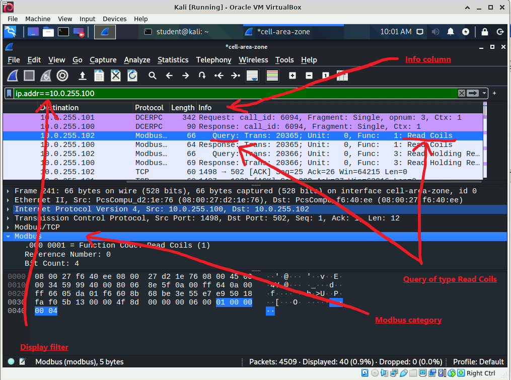
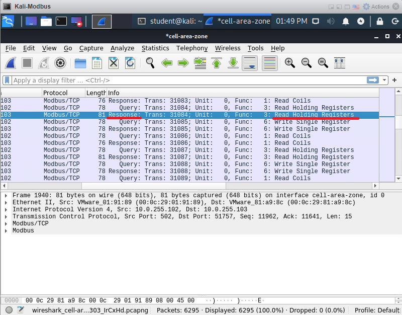
If necessary scroll to the right in the top, packet list panel, until you are able to view the data shown in the Info column (Example).
The standard Wireshark output window is divided into three panels, the top panel is named the packet list panel and contains a summary of each packet captured.
The middle panel is named the packet details panel and shows a decoded view of the packet currently selected in the packet list panel.
The bottom panel is named the packet bytes panel and shows the raw data contained in the packet currently selected in the packet list panel.
Scroll through the packets in the top packet list panel until you find a packet labeled as a Response to a Read Holding Registers request (Example).
In the top packet list panel, select the packet containing Info related to a Response: associated with a Read Holding Registers request.
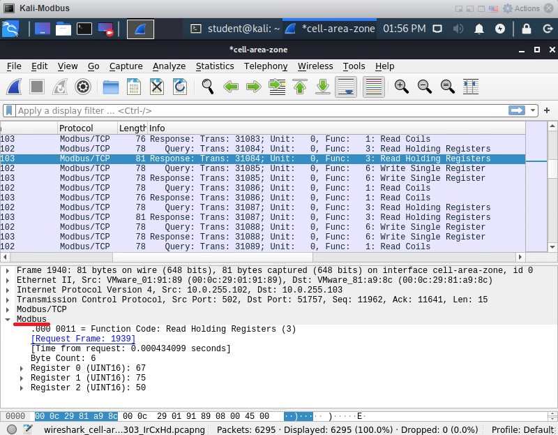
In the middle packet details panel expand the Modbus category of detail data (Example).
Make a note of the data contained in Register 0, Register 1 and Register 2.
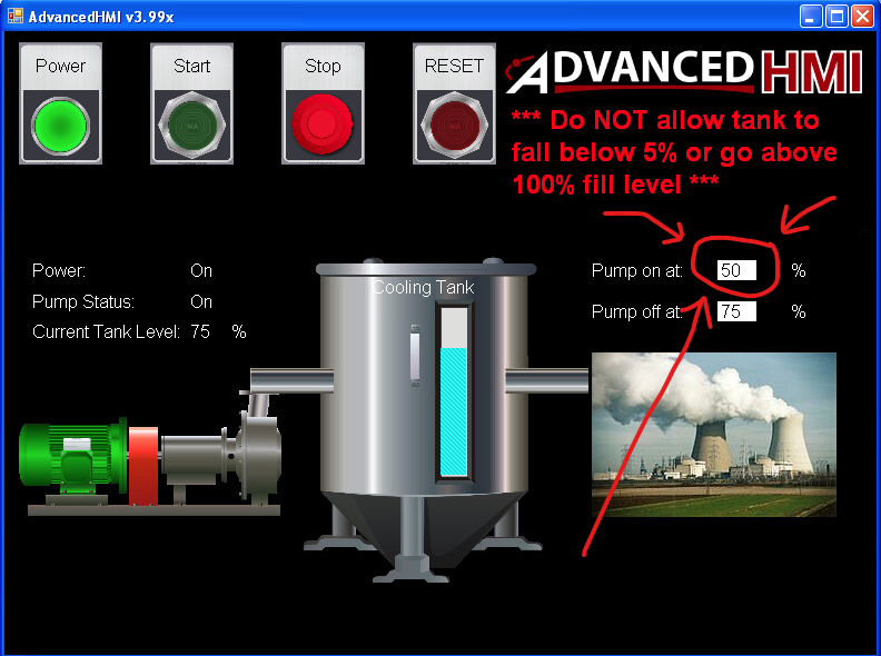
Access the HMI virtual machine and take a moment to examine the data and controls available in the running AdvancedHMI program.
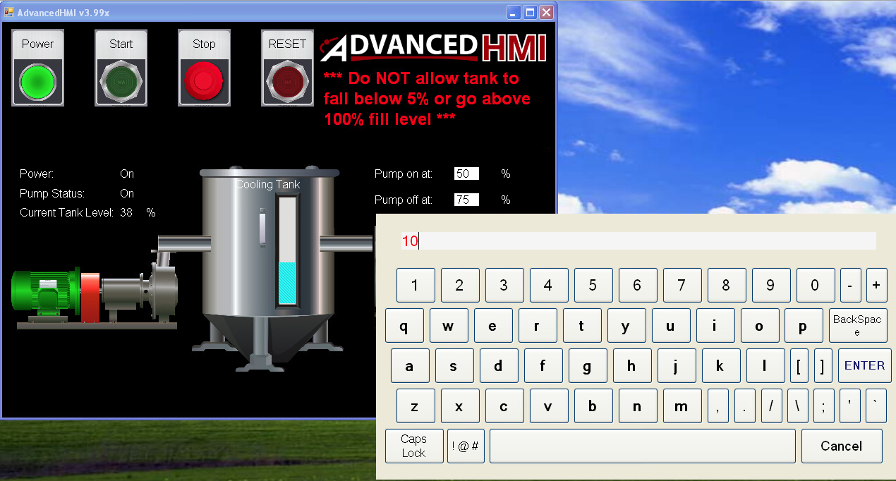
Click on the value shown in the Pump on at: field (Example).
Take a minute to observe how this modifies the behavior of the system.
Access the Kali system.
Begin a new network data capture by accessing the Capture menu in Wireshark and choosing the Start option.
Click the Continue without Saving button when you are informed that there are unsaved packets in the problem
The data you need to view will be captured very quickly so immediately return to the Capture menu and select the Stop option.
Scroll through the packets in the top packet list panel until you find a packet labeled as a Response to a Read Holding Registers request.
In the top packet list panel, select the packet containing a Response to Read Holding Register request.
In the middle packet details panel expand the Modbus category of detail data.
Take a screen shot showing the data in Register 0, Register 1 and Register 2 (Example) and paste it into the Zoning Lab Form found here.
Based on the packets captured it appears that the value in Register 2 tells the system to turn the pump on when the level of liquid drops to 10%. What do the values stored in Registers 0 and 1 represent? Answer these questions in the previously downloaded Zoning Lab Form.
Part 4
Change the hacker's network segment
In this part of the lab you are going to remove the hacker from the network containing the ICS systems. The hacker system will be moved from the Cell/Area zone to the Manufacturing zone (Network diagram).
Close the Wireshark program without saving any data.
Access the terminal (command prompt).
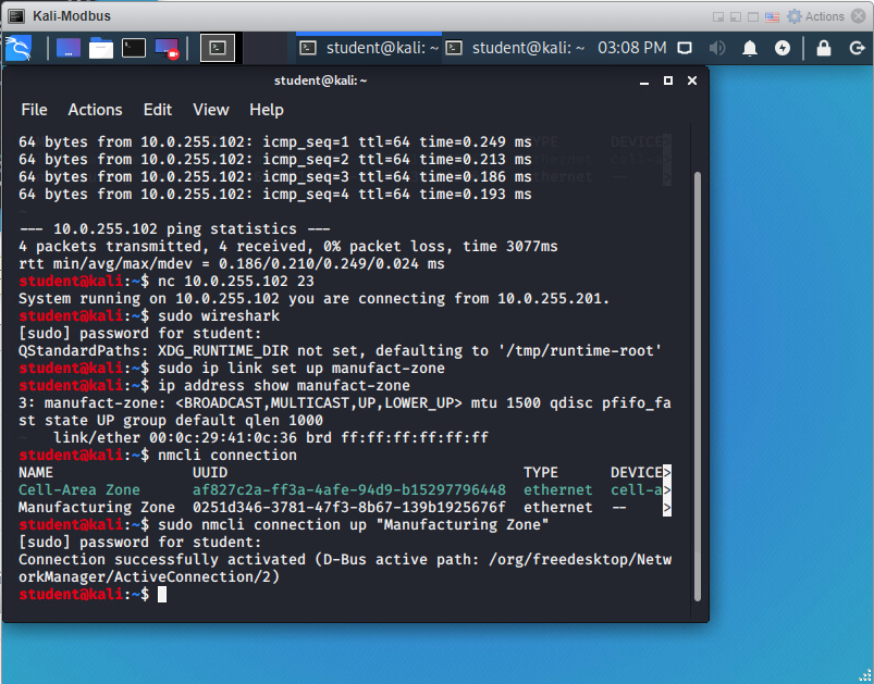
Bring up the network device connected to the manufacturing zone network segment using the command sudo ip link set up manufact-zone (Example).
If you are using sudo and are prompted to authenticate type in the password Password01 followed by the <ENTER> key.
Verify that the device is connected to the network by typing the command ip address show manufact-zone and verifying from the output that the device's state is UP but that it has not yet been assigned an IP address.
View the available network configurations by typing the command nmcli connection.
Notice that the Cell-Area Zone configuration is associated with a device but the Manufacturing Zone configuration is not.
Type the letter q to stop viewing the network configurations.
Enable the Manufacturing Zone network configuration by typing the command sudo nmcli connection up "Manufacturing Zone" (Example).
Verify that the Manufacturing Zone configuration is now associated with a device by again typing the command nmcli connection.
Type the letter q to stop viewing the network configurations.
Verify that the manufact-zone device has been assigned an IP address by again typing the command ip address show manufact-zone.
To prevent confusion later disable the Cell-Area Zone configuration by typing the command sudo nmcli connection down "Cell-Area Zone" .
Verify that now the Manufacturing Zone configuration is associated with a device but the Cell-Area Zone configuration is not by typing the command nmcli connection.
Type the letter q to stop viewing the network configurations.
Part 5
Capture and view data transmitted in the Manufacturing zone
In this part of the lab you are going to use the Wireshark network monitoring software to capture and view data being transmitted on the Manufacturing zone.
Verify that the hacker can communicate with the PLC by typing the command ping 10.0.255.102 -c 4 and observing that 4 packets are transmitted and 4 packets are received.
Verify that the PLC is running by typing the command nc 10.0.255.102 23 and observing that the PLC is running, and that the IP address of the PLC and the address of the connecting system is shown.
Note that this time the Kali system is on a different IP network (10.0.105.0/24) than the ICS systems (10.0.255.0/24).
Start the Wireshark program by typing the command sudo wireshark.
After the Wireshark program starts select the manufact-zone network device to indicate that you wish to capture data on that device.
Click the Capture menu then select the Start option.
Wait a few moments and note that little to no network traffic is currently being captured.
Access the HMI virtual machine.
Click on the value shown in the Pump off at: field in the AdvancedHMI program running on the HMI virtual machine.
Change the pump off value to 60.
Observe the system for a minute and verify that this change modifies the behavior of the system.
Return to the Kali system and note that none of the changes or activity between the ICS systems has been captured.
Open a new Terminal (command prompt) window by clicking the Terminal Emulator button found at the upper left hand corner of the Kali system.
Ping the PLC by typing the command ping 10.0.255.102 -c 4.
Return to the Wireshark screen and notice that since the Kali system was involved in the network communication the ping (ICMP) traffic was captured.
Stop the network traffic capture by accessing the Capture menu and selecting the Stop option.
Take a screen shot showing a captured ping (ICMP) request and reply and paste it into the previously downloaded Zoning Lab Form.
In the previously downloaded Zoning Lab Form answer the question "Why was the network ping traffic between the Kali system and the PLC captured but the data between the PLC and other ICS systems was not?".
In the previously downloaded Zoning Lab Form answer the question "If using proper zoning techniques is more secure why might companies not configure their systems using this technique?".
To end the lab, restart the ICS Lab Control program from the Desktop if necessary, select the Pause/End Lab option, click the OK button then wait for the systems to stop.