The industrial control system (ICS) used in this scenario simulates an environment that might be used to cool industrial equipment. The ICS is made up of five systems. The first system contains a tank, tank level sensor and a water pump. The second system is a programmable logic controller (PLC) which controls the water pump based on the level of water found in the attached tank. The third system is an Open Platform Communications (OPC) server which accesses and modifies data found on the PLC. The fourth system is running Human Machine Interface (HMI) software which communicates with the OPC server to provide a human system operator with system statistics and control. The final system in the ICS is a security appliance that provides routing and firewall services for all systems.
This scenario also make use of a system running Kali Linux. In this lab the virtual network switch is configured so that the Kail system receives all data transmitted. (Network diagram)
In this lab you are going to observe that when a hacker is connected to the same network segment as the ICS systems, they are easily able to view data being shared between all devices. After verifying this you will move the hacker system to its own network and again attempt to view data being transferred. You will discover that when a hacker is connected to a different segment then the ICS systems they are no longer able to view data transfers.
Part 1
Install Systems
In this part of the lab you are going to install and configure the systems needed to complete the lab.
After the import has completed access the Settings for the Security Appliance virtual machine and change its configuration so that it is bridged to the network device in your host computer.
Power on the systems in the following order:
Security Appliance
Sensor
PLC
OPC
HMI
Kali
Part 2
Login and configure the network settings
In this part of the lab you are going to login to the hacker system, connect it to the appropriate network then verify that it can connect to the PLC.
Access the Kali system.
At the login screen enter student into the Enter your username field and Password01 into the Enter your password field.
Click the Log In button.
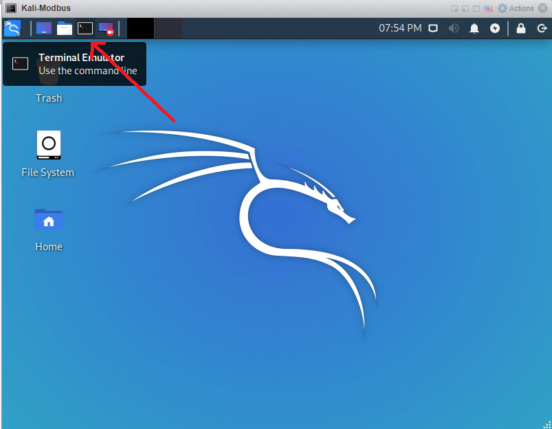
Open a terminal (command prompt) window by clicking the Terminal Emulator button found at the upper left hand corner of the window (Example).
Type the command nmcli connection to view the available network connections.
Notice that the Cell-Area Zone configuration is associated with a device but the Manufacturing Zone configuration is not.
Type the letter q to stop viewing the network configurations.
Switch the zone (network segment) that the Kali system is connected to by typing the command ./change_network.sh then providing the student user's password, Password01 when prompted.
To prevent people from looking over your shoulder and writing down the password it is not displayed on the screen as you are typing.
View the available network configurations by typing the command nmcli connection.
Notice that now the Manufacturing Zone configuration is associated with a device but the Cell-Area Zone configuration is not.
Type the letter q to stop viewing the network configurations.
Verify that the PLC is running by typing the command nc 10.0.255.102 23 and observing that the PLC is running, and that the IP address of the PLC and the address of the connecting system is shown.
The nc command starts the netcat program which is a useful network utility that allows a quick connection to network services. In this case netcat is connecting to the telnet service running on the PLC.
Note that the Kali system is on a different IP network (10.0.105.0/24) then the ICS systems (10.0.255.0/24).
Part 3
Enable and test an Intrusion Detection System (IDS)
In this part of the lab you are going to enable the Snort as an IDS, configure a rule to detect Modbus traffic and then test the rule.
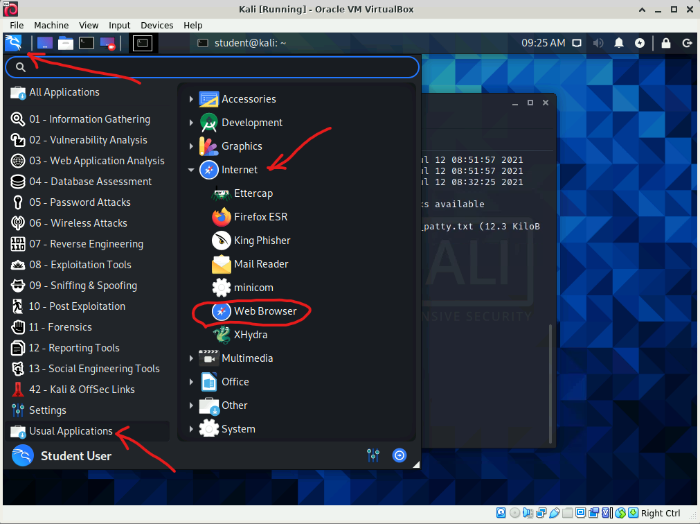
Start a web browser on the Kali system by clicking the Application menu button at the top left of the screen, scrolling down the list of application folders then clicking the Usual Applications folder, expanding the Internet category and finally clicking on the Web Browser option ( Example ).
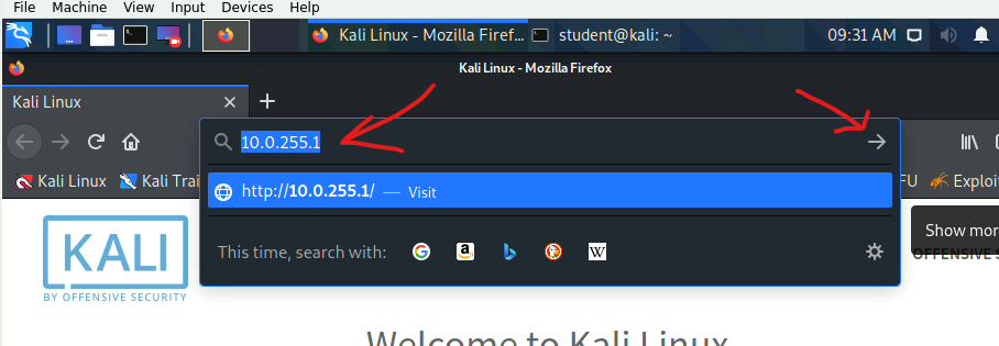
Type the address 10.0.255.1 into the Web Browser's address bar then click the Go to the address in the Location bar button ( Example ).
If necessary, click the Advanced... button when you see the Warning: Potential Security Risk Ahead web page, read the explanation for the security warning then click the Accept the Risk and Continue button.
Type the username admin into the Username field.
Type the password Password01 into the Password field.
Click the SIGN IN button.
If you are asked if you would like Firefox to save the login data, click the Don't Save button.
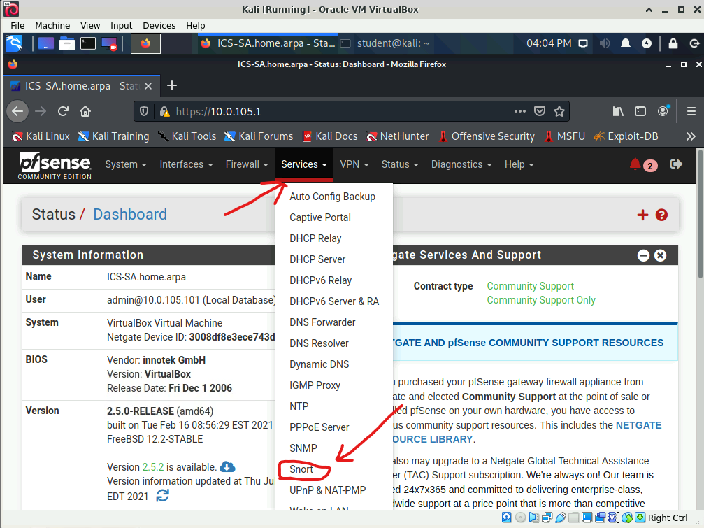
Expand the Services category at the top of the administrative console page then choose the Snort option ( Example ).
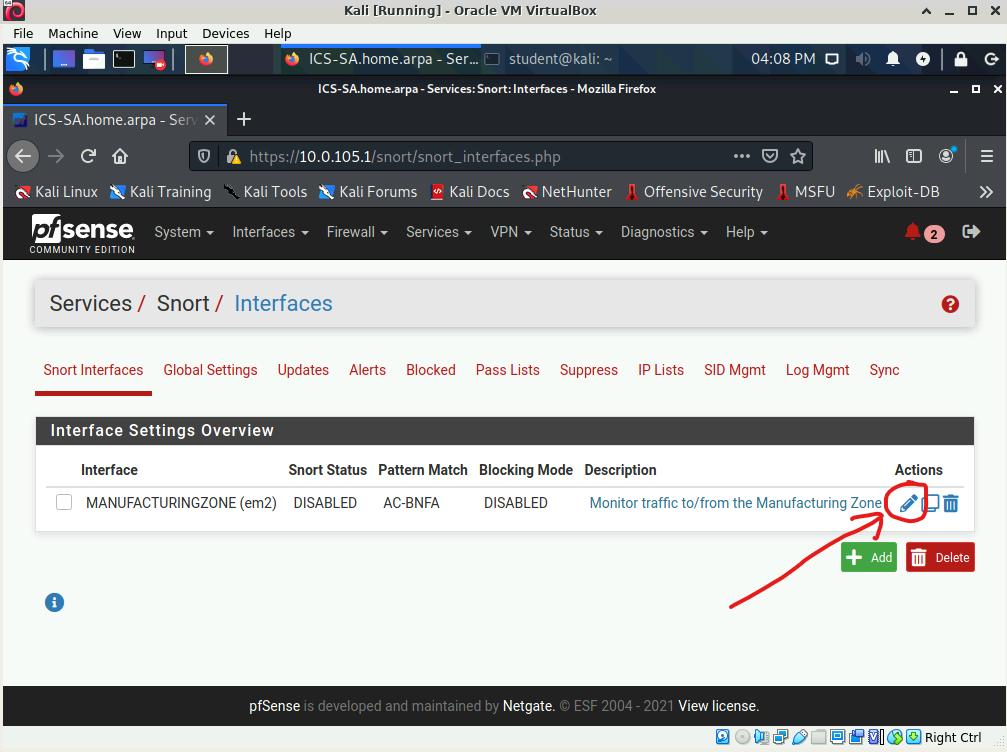
Click the Edit icon associated with the MANUFACTURINGZONE (em2) interface ( Example ).
In the General Settings category located at the top of the web page, put a check into the box labeled Enable interface.
Scroll to the bottom of the page then click the Save button.
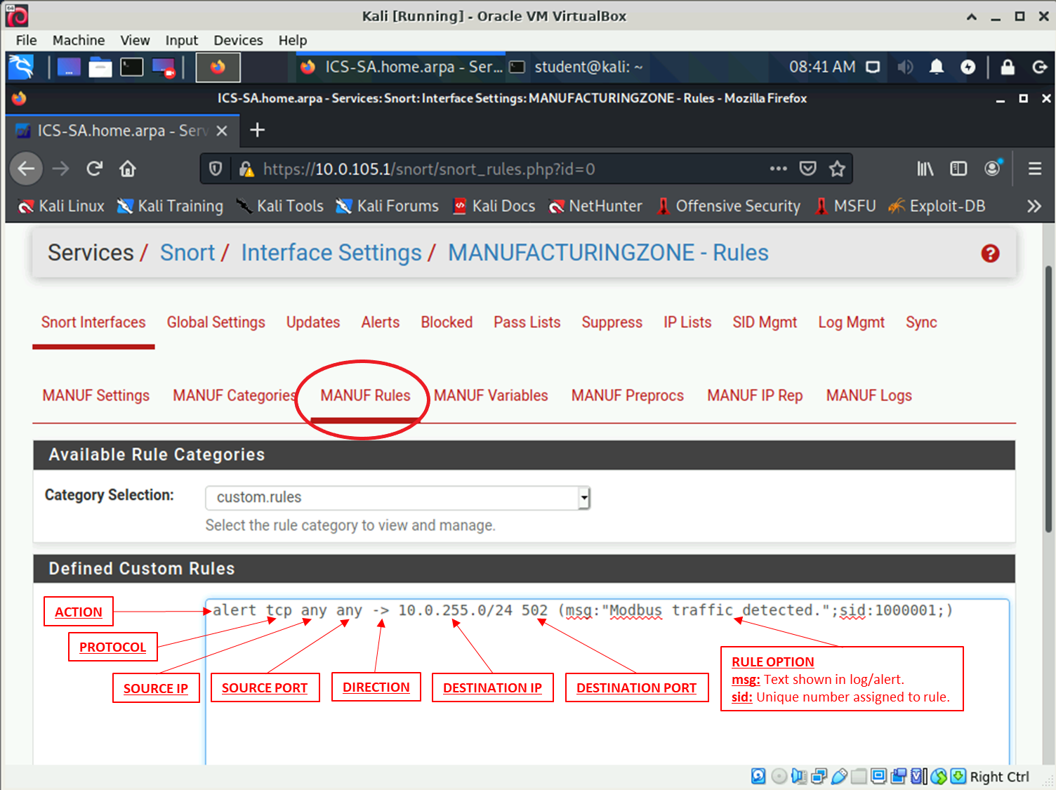
Type the rule alert tcp any any <> 10.0.255.0/24 502 (msg:"Modbus traffic detected.";sid:1000001) into the Defined Custom Rules text box ( Example ).
Snort rules are made up of eighth components:
First, is the action that should be taken if traffic matching the rule is found. The alert action indicates that snort should generate an alert and log the packet.
Second, is the protocol that the rule should match. The tcp keyword indicates that TCP traffic should match.
Third, is the source IP that the rule should match. The any keyword indicates that any source IP should match.
Fourth, is the source port that the rule should match. The any keyword indicates that any source port should match.
Fifth, is the direction of traffic that the rule should match. The <> symbols indicates that traffic going in either direction should be matched.
Sixth, is the destination IP that the rule should match. The network address 10.0.255.0/24 indicates that this rule should match any IP in the address range 10.0.255.1 - 10.0.255.254.
Seventh, is the destination port that the rule should match. The tcp port 502 indicates that this rule will match traffic destined for port 502 (Modbus traffic).
Eighth, are the options that should apply to the rule. The msg: option is text that will be used to describe the rule if it matches network traffic. The sid is a unique number assigned to the rule.
Before going to the next step double check your typing as a typo in the rules will prevent Snort from starting.
Scroll to the bottom of the page then click the Save button.
Click the Snort Interfaces link.
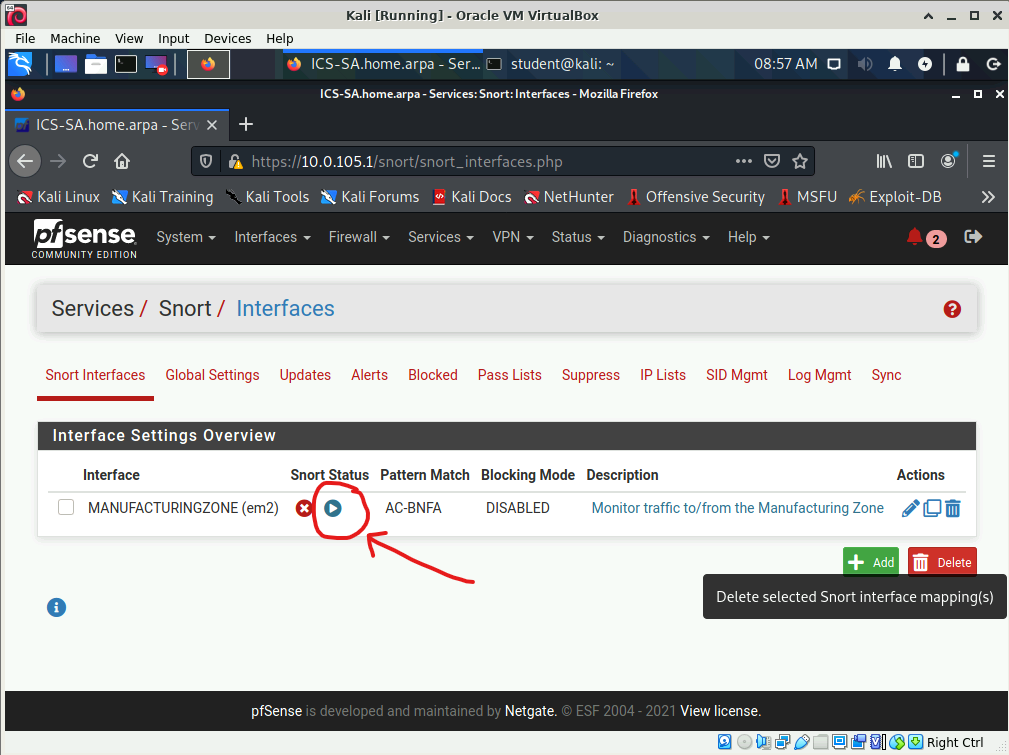
Click the Start button associated with the MANUFACTURINGZONE (em2) interface ( Example ).
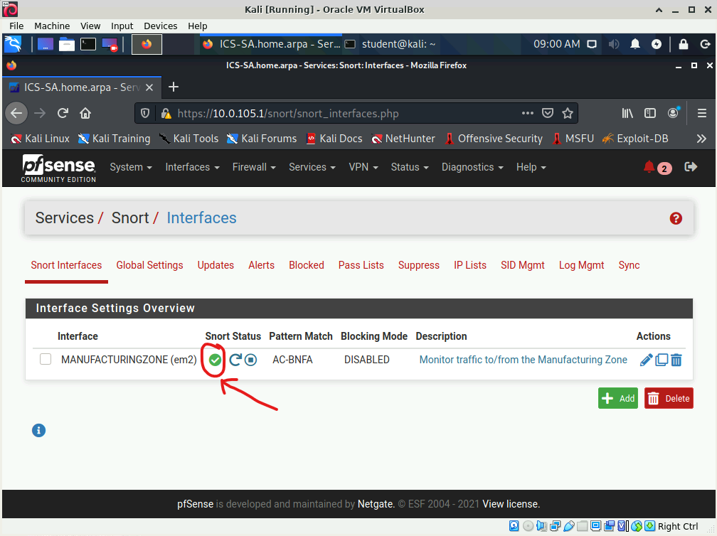
Before going to the next step verify that the Running icon appears indicating that Snort started successfully ( Example ).
If Snort does not start edit the MANUFACTURINGZONE (em2) interface's rules and verify that the rule is typed in exactly as shown here.
Access a terminal window on the Kali system.
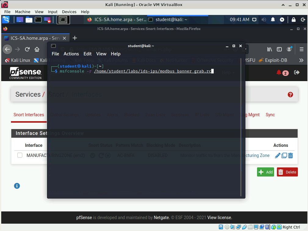
Type the command msfconsole -r /home/student/labs/ids-ips/modbus_banner_grab.rc to use the Metasploit program to retrieve the banner from the PLC ( Example ).
Access the pfsense web page using the Kali system.
If necessary, expand the Services category at the top of the administrative console page then choose the Snort option.
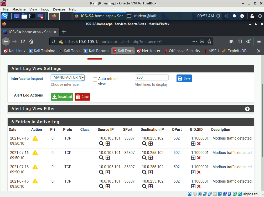
Click the Alerts link.
Scroll down that page and observe the alerts that the Metasploit program generated.
Take a screen shot that shows the entire Kali window ( Example ) and paste it into the IDS/IPS Lab Form found here.
Part 4
Configure IDS Packet Capture
In this part of the lab you are going to configure the Snort IDS to capture packets matching alert rules and then use the Wireshark program to analyze the data.
Access the pfsense web page using the Kali system.
If necessary, expand the Services category at the top of the administrative console page then choose the Snort option.
Click the Snort Interfaces link.
Click the Edit icon associated with the MANUFACTURINGZONE (em2) interface.
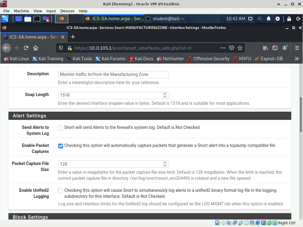
Scroll down the page until you locate the Alert Settings options.
Place a check in the Enable Packet Captures check box ( Example ).
Scroll to the bottom of the page then click the Save button.
Access a terminal window on the Kali system.
Type the command msfconsole -r /home/student/labs/ids-ips/modbus_banner_grab.rc to use the Metasploit program to retrieve the banner from the PLC ( Example ).
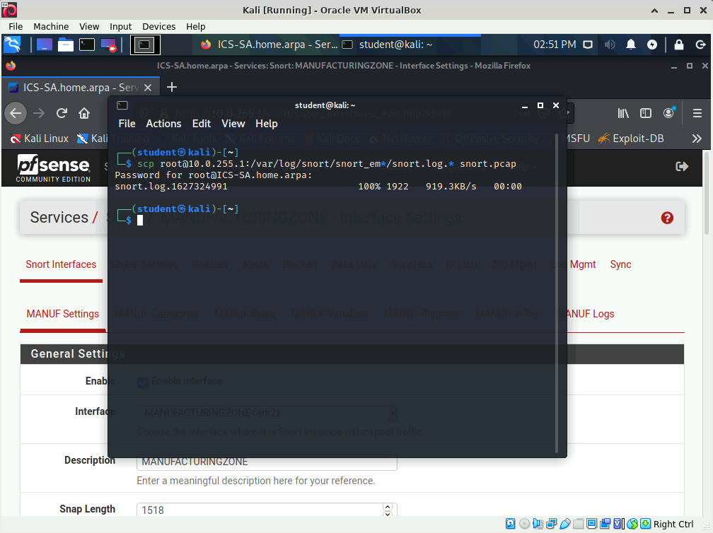
Type the command scp root@10.0.255.1:/var/log/snort/snort_em*/snort.log.* snort.pcap to tell the scp program to copy the packet capture from the Security Appliance to the Kali system ( Example ).
Type the password Password01 then press <ENTER> when prompted ( Example ).
When packet capturing is enabled Snort will save a packet capture file named snort.log.uniquevalue in the /var/log/snort/snortinterfacename directory. Using the wildcard * allows the file to be copied without first having to determine what value pfsense has assigned to the interface or packet capture file.
Type the command wireshark to start the Wireshark program.
From the File menu in Wireshark choose the Open option.
Navigate to the /home/student directory then open the snort.pcap capture file.
Take a minute to view the captured data.
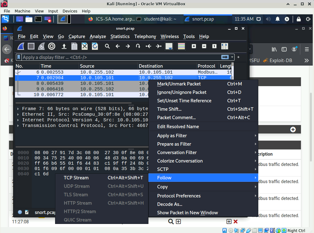
Right click any packet in the top, packet list, pane
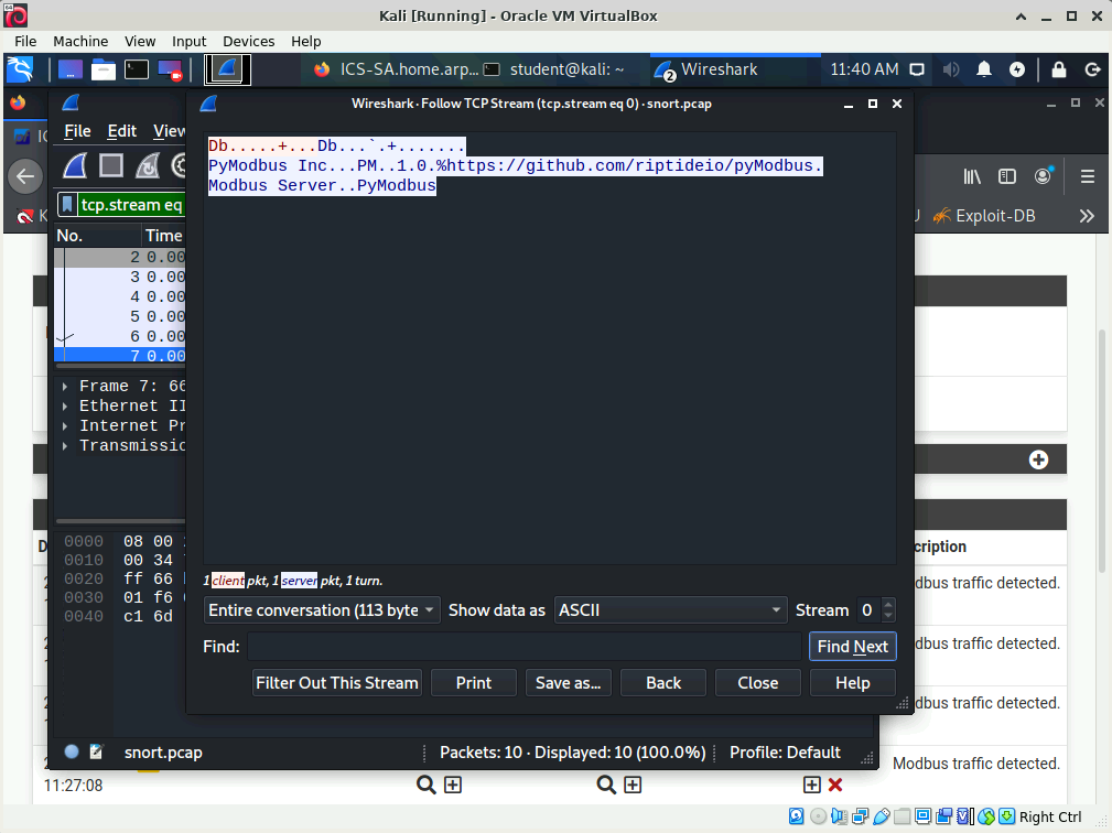
then from the pop up menu choose the option Follow -> TCP Stream ( Example ).
Take a screen shot that shows the entire Kali window ( Example ) and paste it into the IDS/IPS Lab Form found here.
Close the Wireshark program.
Part 5
Enable and test an Intrusion Prevention System (IPS)
In this part of the lab you are going to enable the Snort as an IPS, test the IPS and observe how it differs from an IDS.
Access the pfsense web page using the Kali system.
If necessary, expand the Services category at the top of the administrative console page then choose the Snort option.
Click the Snort Interfaces link.
Click the Edit icon associated with the MANUFACTURINGZONE (em2) interface.
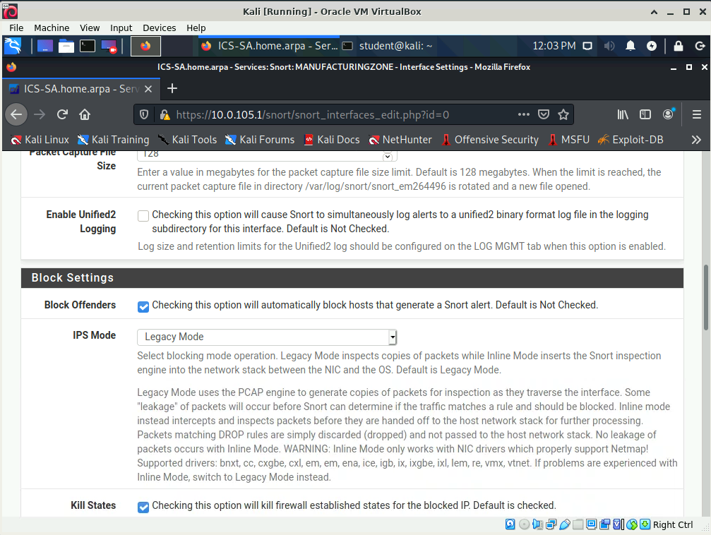
Scroll down the page until you locate the Block Settings options.
Place a check in the Block Offenders check box ( Example ).
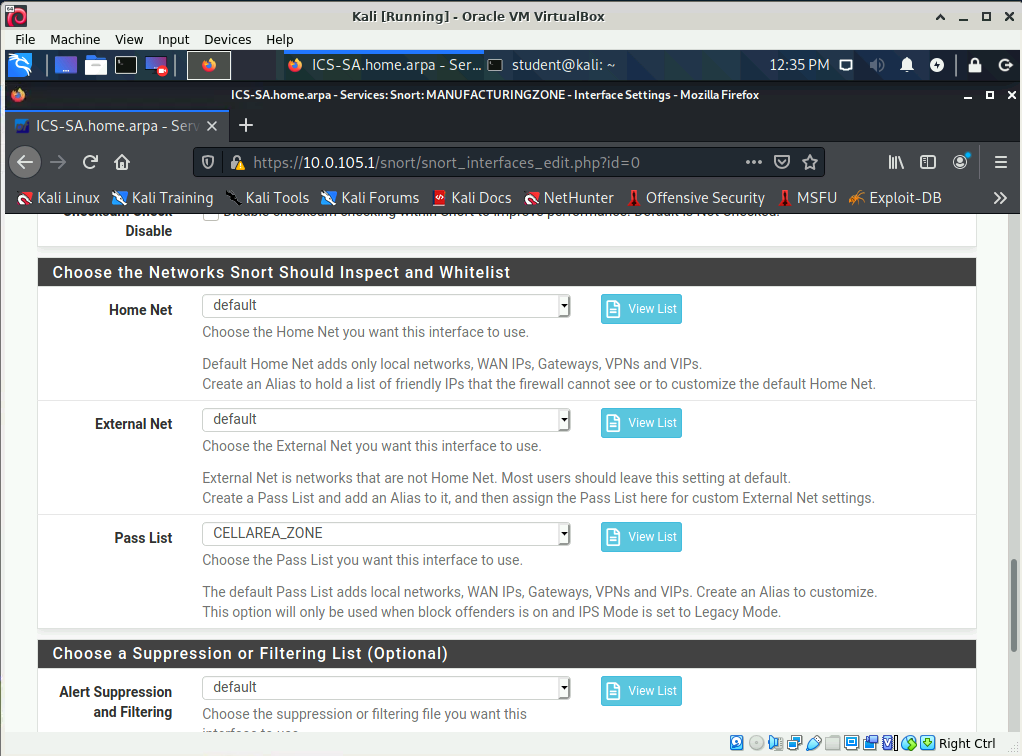
Scroll down the page until you locate the Choose the Networks Snort Should Inspect and Whitelist options.
Select the CELLAREA_ZONE pass list from the Pass List pull down menu ( Example ).
Scroll to the bottom of the page then click the Save button.
Access a terminal window on the Kali system.
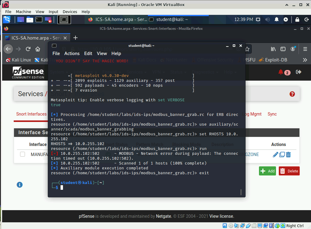
Type the command msfconsole -r /home/student/labs/ids-ips/modbus_banner_grab.rc to use the Metasploit program to retrieve the banner from the PLC.
Attempt to execute the command msfconsole -r /home/student/labs/ids-ips/modbus_banner_grab.rc a second time and note that the connection times out.
Take a screen shot that shows the entire Kali window ( Example ) and paste it into the IDS/IPS Lab Form found here.
Access the pfsense web page using the Kali system.
If necessary, expand the Services category at the top of the administrative console page then choose the Snort option.
Click the Blocked link and notice that the page will not load